Shop Work Page #21

This webpage shows the current jobs
being worked on in the shop.
Hope you enjoy the activity.
Page 1, Page 2, Page 3, Page 4, Page 5, Page 6, Page 7, Page 8, Page 9, Page 10, Page 11, Page 12, Page 13,
Page 14, Page 15, Page 16, Page 17, Page 18, Page 19, Page 20, Page 21, Page 22, Page 23, Page 24, Page 25,
Page 26, Page 27, Page 28, Page 29, Page 30, Page 31, Page 32, Page 33, Page 34, Page 35, Page 36, Page 37,
Page 38, Page 39, Page 40, Page 41, Page 42, Page 43, Page 44, Page 45, Page 46, Page 47, Page 48, Page 49, Page 50,
for more Shop Work.
03/23/04
In these (2) photos you can see some brass castings I had made. There are (3) sets of brasses, (2) halves for each set. They are for 15 HP Titusville Olin engines. In photo #1 you can see an original brass half that was built up with plywood and fiberglass to use as the pattern. Photo #2 is a close up of (2) of the brasses...


In photo #1 the clean up of the wrist pin holes on the Watkins piston is complete. With the metal spraying process, the wrist pin holes fill up with an over spray of the material. Also some final sanding and polishing was done on the piston. Photo #2 shows the Watkins piston completed and waiting for new piston rings...


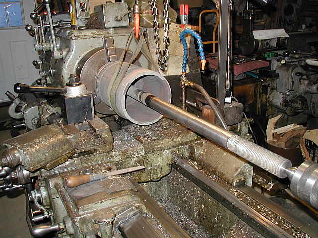
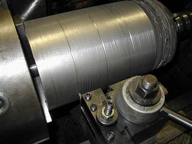
These (2) photos show starting to get the Braden piston in the lathe for turning. The first operation is to clean up the back side of the piston. Photo #2 shows taking a few passes on the back side of the piston. Note the over spray of material on the connecting rod. There is a release agent painted on the connecting rod before metal spraying, so this over spray will clean right off...

03/24/04
Photo #1 shows the connecting rod all polished up. This diameter needs to be real smooth as a packing glade seals the scavenging side of the cylinder around the rod. Photo #2 is of turning the piston and connecting rod assembly around in the lathe. Photo #3 & #4 show starting to turn the OD of the piston...


03/26/04 & 03/27/04
The first photo shows the OD of the Braden piston almost completed. Photo #2 shows the Braden piston OD turned to it's final diameter. Photo #3 shows cutting (3) oil grooves...


Photos #1 & #2 show truing up the piston ring grooves. Photo #3 shows the piston moved away from the chuck and the sharp edge on the back being chamfered...


03/28/04
After removing the piston and connecting rod from the lathe, It was tried in the new cylinder bore...


The next part to be fabricated is a new packing gland. This is the part that will seal around the connecting rod. Photo #1 shows the existing packing gland which is broke into a few pieces. Photo #2 is of a drawing I made for the new packing gland...


This series of photos show a round flat plate in the lathe being drilled, with the last photo showing boring the hole to final size to fit the mating center section...


Photos #1 & #2 show welding the (2) pieces of the packing gland together. Photo #3 shows (2) welds put on the connecting rod and the jam nut. This will insure the nut doesn't come off when the engine is running...


Now the packing gland is put back in the lathe with the back face being trued up...


03/30/04
In the first and second photo you can see that I am working the carbide insert tool pretty good. The camera flash on the smoke, makes it look worse then it really is. Photo #3 shows the packing gland back side all faced off. Photo #4 shows turning the OD of the packing gland back plate to size...


Next is to drill a hole through the packing gland and get ready to bore the hole that the connecting rod will go through. Photo #2 shows just finishing up drilling a 1.500 diameter hole through the part...


03/31/04
In the first photo here you can see the packing gland is turned around in the lathe. Photo #2 shows turning the OD of the center portion, and photo #3 shows it turned to size. Next will be to face off the large backing plate...


04/01/04
Photo #1 shows the back plate of the packing gland being faced off. Photo #2 shows the parting tool cutting the main part of the packing gland to length. Notice the chip coming off the tool in photo #3...


The first photo shows the cutoff complete and the scrap cutoff piece hanging on a shaft that is held in a chuck on the tailstock. In photo #2 you can see the cutoff completed. Photo #3 shows starting to bore the ID of the packing gland...


04/02/04
Here in photo #1 you can see the packing gland ID finished to 1.680. Photo #2 shows turning the angle where the actual packing material will seal around the connecting rod. Photo #3 shows the completed bore and angle...


04/03/04
On April 3rd, 2004 Doug Allen had a small get together of some local engine enthusiast, and below are a few photos from the event. The main feature of the get together was the 35 HP Black Bear engine that Doug has just completed restoring. It ran beautiful. What a nice engine collection Doug has built over the years. He has done a great job restoring his engines. Hope you enjoy the photos...


04/04/04
Photo #1 shows the layout of the (2) holes that will mount the packing gland to the back side of the cylinder. The next (2) photos show drilling the .750 diameter holes...


These (2) photos show the packing gland all deburred and completed...


In this photo I have a piece of .750 diameter stock in the lathe chuck, and am getting it set up to cut a 3/4-10 thread. This will be a stud for mounting the cylinder head...

04/05/04
One of the cylinder head mounting studs for the Braden engine was broken, so one was made up quick. The first photo shows one of the original studs. They are 6.312 LG. and the thread size is 3/4-10. Photo #2 shows the thread starting to take shape. Photos 3 & 4 show the completed thread...


These next few photos show threading the other end of the stud. Photo #1 shows the actual threading being done. Photo #2 shows the completed thread and photo #3 shows the original and new stud side by side...


Shop Work Continued on Page #22
Page 1, Page 2, Page 3, Page 4, Page 5, Page 6, Page 7, Page 8, Page 9, Page 10, Page 11, Page 12, Page 13,
Page 14, Page 15, Page 16, Page 17, Page 18, Page 19, Page 20, Page 21, Page 22, Page 23, Page 24, Page 25,
Page 26, Page 27, Page 28, Page 29, Page 30, Page 31, Page 32, Page 33, Page 34, Page 35, Page 36, Page 37,
Page 38, Page 39, Page 40, Page 41, Page 42, Page 43, Page 44, Page 45, Page 46, Page 47, Page 48, Page 49, Page 50,
for more Shop Work.
 |
Antique Gas Engine WebSite |
|
 Website designed and maintained by , Pavilion, NY.
Lunarpages Affiliate Program

Registered User #157284
Sun, Sparc, Ultra60 running Aurora 1.0 (RedHat Linux 7.3)
in mind, and are meant entirely for fun. No copyright infringements (if any) are done intentionally.