Shop Work Page #15

This webpage shows the current jobs
being worked on in the shop.
Hope you enjoy the activity.
Page 1, Page 2, Page 3, Page 4, Page 5, Page 6, Page 7, Page 8, Page 9, Page 10, Page 11, Page 12, Page 13,
Page 14, Page 15, Page 16, Page 17, Page 18, Page 19, Page 20, Page 21, Page 22, Page 23, Page 24, Page 25,
Page 26, Page 27, Page 28, Page 29, Page 30, Page 31, Page 32, Page 33, Page 34, Page 35, Page 36, Page 37,
Page 38, Page 39, Page 40, Page 41, Page 42, Page 43, Page 44, Page 45, Page 46, Page 47, Page 48, Page 49, Page 50,
for more Shop Work.
05/28/03
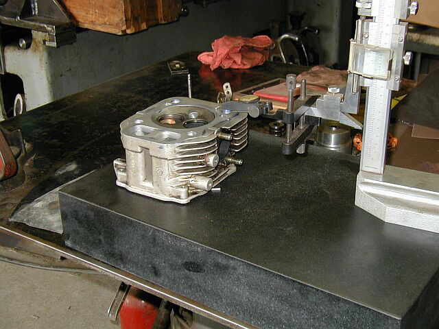
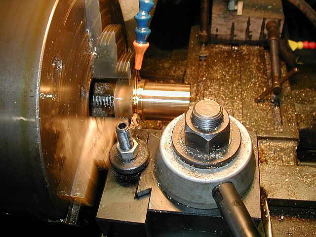
In these first (2) photos you can see the new seat being re-cut with a 45 deg. angle. In the second photo the valve is being re-ground. Both exhaust and intake valves were re-ground and lapped in. 3 years ago when I bought this Power King garden tractor with the 18 HP over head valve Kohler engine on it, the head was warped from a blown head gasket. I think this was why the tractor was sold. I put the head in the lathe and trued the head mounting surface by removing .021 from it. It was recommended by a local engine shop where I got the new valve seats from that I try to get the engine back to the original compression numbers by putting in a copper gasket along with the new head gasket. The copper gasket will go next to the cast iron block and the new head gasket will go towards the aluminum head side. This will help get the engine temperature back to normal. In these last (2) photos you can see the copper head gasket that I made. Now to get the engine back together and see how it runs...


05/30/03
Well the engine is back together and I have put a total of about 3 hours run time on it. In these (2) photos you can see the head all mounted and torqued. After about 1 hour of running I re-torqued the head bolts and everything seems to be working fine. It actually feels like a new engine when cutting the grass...


05/31/03 - 06/01/03
In the following photos you can see some work I did on my cement mixer to fix things up. The first thing I did was fabricate a couple of skid rails. The ends were cut and formed up, and then welded. The (2) rails where then welded to the bottom of the mixer frame. Next was to fabricate a pivoting motor mount so the drive belt would always have tension on it. The mount was made out of a piece of 6" C-channel and pivots on a 7/8" diameter pin. It seems to be working real good. The real test will be when the drum is fully loaded. Guess what work is next...


These next few photos are of a small flange Ron Polle is making that mounts onto the water jacket of a 3 1/2 HP Petter diesel engine that Ron just purchased. The hole in the center is 1/4 NPT thread to accept a fitting for a temperature gage. Ron just has a little finish grinding to do to complete the part...


06/02/03 - 06/04/03
My son Christopher and I are getting the 25 HP Swan ready for a trip to the June Coolspring Engine show. In the first (2) photos you can see Christopher hard at work. In the next (2) photos we had everything almost completed with the engine all bound down to the trailer and ready for the trip...


06/08/03
With the 25 HP Swan all ready for the trip to Coolspring, we headed south to Pa. You can see in these (4) photos getting the engine off the trailer, bringing the engine into the Harvey Expo building, and setting the Swan engine in place. I would like to say thanks to everyone who helped out, Jay Duke, Dr. Paul Harvey, Chris Austin, and Stiles Bradley. Next we'll get the engine all plumbed up and ready to run...


06/17/03 - 06/19/03
It was a few days before the June show was to start and it was time to get the Swan plumbed in. I would like to thank Doug Allen, Otto Dole, Chris Austin, and Stiles Bradley for helping me get this job done. Everyone helped get the ditch dug for the exhaust for both the Swan and the Backus engine. We decided to plumb up Paul Harvey's 14 HP Backus because the exhaust pipes could lay in the same ditch and we could also run the engine during the show. In some of the photos you can see Otto and Doug, heating up some existing plumbing to get it a part, and also Doug and Chris filling in the ditches after all the pipe had been put in place. The last few photos show the Backus and the Swan all plumbed up and ready for the show. Thanks again to everyone for helping get this job completed. Thanks...


06/25/03
In these next (6) photos I am machining the mounting surface of a valve chest for a 18 HP Buffalo Olin. The original surface was all pitted and very uneven. I set the valve chest up on the shaper and trued the mounting surface up. You can see in the last photo how it came out...


06/29/03
My friend Ron Polle came over the shop and we started building a water tower tank cooler for one of his diesel engines that he is adding a generator to, so he can generate his own power. It's going to be a thermal siphon system so the tank needed to be off the ground about 38". We'll have to get some photos of the completed engine / generator project when Ron gets it completed. Below you can see a few photos of the start of the water tower and tank...


06/30/03
Below are some photos of a head, off of a 25 HP Kohler twin engine. If you look close in the first photo you can see the engine had a blown head gasket. The extra heat had warped the head around .007 in the area where the head gasket blew. I took the valve out and checked them a long with checking the clearance between the valve stems and the guides. They checked out okay. I ground the valves and recut the seats, then lapped them in. Next I trued the head up on a surface plate by blueing the head gasket mounting surface and checking for low spots. After repeated times of this, I put the head on the surface plate and checked flatness with an indicator. Finally the entire surface was within .0005 TIR. The photos below show the work as it progressed to the last photo which is of the assembled head, ready to go back on the engine...


07/02/03
Below are (2) photos of the water cooling tower. The first one shows the tower with all the cross bracing and the flanges screwed on the bottom of the legs. Then the second photo shows the completed water cooling tower all painted and ready for action. The water cooling tower came out real nice Ron. We'll have to get a photo of the cooling tower with the water tank in place and it cooling the diesel engine...


07/13/03
Well I have changed the way I am going to bore the Flickinger Corliss box. What I am going to do is run or turn the boring bar in (2) bushings which locate off the (2) packing nuts. This way I will be boring right to the existing bore. In some of the photos below you can see the making of the (2) bushings and also of some other work going on in the shop. One photo shows my oldest son Joseph welding up a steel frame to use as a dolley in the shop. There also is another photo of my youngest son Christopher painting the outside of the shop. The shop is long over due needing a coat of paint. The setup of the new boring bar setup will become more clearer as I assemble the bar and bushings into the Corliss box and get the photos up on this page...


07/14/03
These next (2) photos are of my son Christopher working on building a skid to mount his Model #92 Maytag. The skid was bought as a kit and he had to sand all the parts and them screw them all together. The second photo shows it all together and the skid ready to be oiled...


07/15/03
In these (2) photos the work is continuing on the new setup for boring the Flickinger Corliss box. The first photo shows boring the bushing to a 1.500 diameter ID. The second photo shows the packing nut and the new bushing pressed into it, mounted on the Corliss box. This is going to make for a real stable setup for boring...


Shop Work Continued on Page #16
Page 1, Page 2, Page 3, Page 4, Page 5, Page 6, Page 7, Page 8, Page 9, Page 10, Page 11, Page 12, Page 13,
Page 14, Page 15, Page 16, Page 17, Page 18, Page 19, Page 20, Page 21, Page 22, Page 23, Page 24, Page 25,
Page 26, Page 27, Page 28, Page 29, Page 30, Page 31, Page 32, Page 33, Page 34, Page 35, Page 36, Page 37,
Page 38, Page 39, Page 40, Page 41, Page 42, Page 43, Page 44, Page 45, Page 46, Page 47, Page 48, Page 49, Page 50,
for more Shop Work.
 |
Antique Gas Engine WebSite |
|
 Website designed and maintained by , Pavilion, NY.
Lunarpages Affiliate Program

Registered User #157284
Sun, Sparc, Ultra60 running Aurora 1.0 (RedHat Linux 7.3)
in mind, and are meant entirely for fun. No copyright infringements (if any) are done intentionally.