Page #8
of the

This engine is a 4 cycle cross head
designed engine with an 11" Bore & 18" Stroke.
There is one huge 5 1/2'
diameter flywheel. The engine was the fore runner
to both the Buffalo and Titusville Olins.
Page 1, Page 2, Page 3, Page 4, Page 5, Page 6, Page 7, Page 8, Index
for more of the 20 HP Abel Acme Restoration project.
Well the head is now starting to take shape. In photo #1 you can see the layout blue on the face used to layout the diameters. Also you can see that I have started cutting out the recess. In photo #2 you can see the inside portion all cut out and edges squared off. In photo #3 the ouside cut and radius are completed and I am getting ready to break all the sharp edges...


The first photo here is a blow/up of the edge cut back with a radius. The depth of the cut back and inside cut is .187. Photo #2 shows all the lathe work on the head almost done. Now I am going to be doing a lot of filing and sanding to get the head really polished up nice...


The valve chest needs to have some work done on it. Photo #1 shows how bad the 3" pipe threads are for the exhaust pipe. Photo #2 is of the 3" tap cleaning up the threads. Photo #3 shows the threads all cleaned up. They cleaned up real good...


Photo #1 shows my friend Ron Polle cutting a template out of cardboard that will be used to layout the hole pattern for the head mounting holes. Photo #2 shows the sanding and polishing of the head all completed. Photo #3 shows the (4) welds that need to be ground away so the tube can be removed and then the mounting holes can be drilled...


Well I am back from 2 weeks vacation so the work will start back up on the Abel Acme engine. In photo #1 I have cut off the tube I used to turn the outside face of the head. Photo #2 shows where I stamped the head "TOP" so the orientation will always be the same when putting it on the engine...


Photo #1 shows the previously hammered out template taped to the head in position for transfering the hole locations. I used layout blueing where each hole is to be located. Photo #2 shows the hole locations all center punched. In photo #3 the head is in the drill press and needs to be clamped before drilling can start. The head is almost the same diameter as the drill press table...


With the head all clamped down the drilling of the holes can take place. Photo #1 shows starting out with a 3/8" diameter drill. I then went to a 3/4" diameter drill next. Photo #2 shows the final drill size of 1 1/16". Photo #3 is of the finished hole. Now only (7) more to go...


Well the head is finally all completed. In photo #1 the last hole is being drilled. In photo #2 the head is all unclamp and ready to be cleaned up. Photo #3 shows the head all cleaned up and de-burred, and sitting in position on the cylinder. I am pretty happy on how the head finished up...


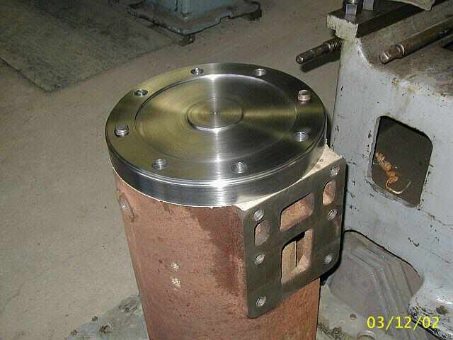
These are a couple of photos with the head and valve chest mounted on the cylinder. Just making sure things are fitting together. So far so good...


With the head all completed its time to move onto some of the other parts needed for the Abel Acme. In these next (2) photos you can see an original link arm that actuates gas valve. Also in photo #1 you can see the spring I am going to use on the gas valve...


Photo #1 shows a piece of 1 1/4" diameter steel in the lathe, center drilled, faced off, and the boss turned for locating the spring and holding it there. Photo #2 is of turning the O.D. of the link down. Photo #3 shows the hole drilled for the gas valve stem, and it inserted into the hole...


In photo #1 you can see that a set screw has been added to the link. I used a short 3/8-16 square headed set screw to hold the gas valve into the link. Photo #2 shows the start of some milling on the gas valve link. This flat runs the entire length of the link so that the jam nut can lock against a flat surface...


Notice
I have stopped working on the Abel Acme restoration for a while to get a few jobs completed for other engine hobbyest. The jobs have been building up and they need to get done. I will be posting photos on the Current Shop Work webpage. Hope you enjoy them...
Page 1, Page 2, Page 3, Page 4, Page 5, Page 6, Page 7, Page 8, Index
for more of the 20 HP Abel Acme Restoration project.
 |
Antique Gas Engine WebSite |
|
 Website designed and maintained by , Pavilion, NY.
Lunarpages Affiliate Program

Registered User #157284
Sun, Sparc, Ultra60 running Aurora 1.0 (RedHat Linux 7.3)
in mind, and are meant entirely for fun. No copyright infringements (if any) are done intentionally.