Page #1
of the

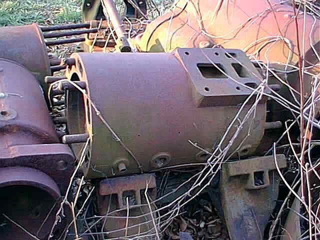
This engine is a 4 cycle cross head
designed engine with an 11" Bore & 18" Stroke.
There is one huge 5 1/2'
diameter flywheel. The engine was the fore runner
to both the Buffalo and Titusville Olins.
Page 1, Page 2, Page 3, Page 4, Page 5, Page 6, Page 7, Page 8, Index
for more of the 20 HP Abel Acme Restoration project.
Here are 2 photos taken quite a few years ago, (20 to 25) of the Abel Acme still in the original power house.


click on the thumbnail for a larger photo...
This first group of photos are of the Abel Acme Engine when I discovered it. Will the engine ever run again?...


A good friend stops by and he helps out starting to load the engine and take it to its new home in Pavilion, NY. The cylinder was the first part to make the trip to NY...


These next few photos are of loading the rest of the Abel Acme Engine parts and getting them north to NY...


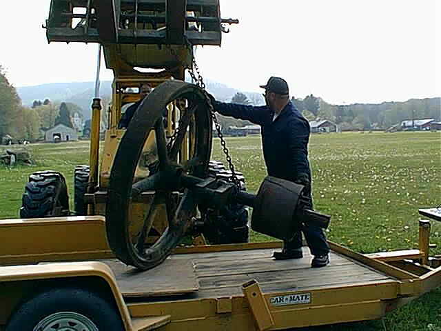


Here are some photos that a friend of mine took when we were loading up the main parts of the 20 HP Abel Acme Engine...


Well the Abel Acme makes the trip north to its new home in Western NY...


In the month of June 2001 I started getting ready to work on the Abel Acme Engine. You can see in these next 4 photos my son and I getting the base in the shop and also putting the cylinder up on the table of the Lucas horizontal boring mill...


In these 3 photos you can see some of the set up for locating the Abel Acme cylinder on the table of the Lucas Horizontal Boring machine. The "C" channel acts like a "V" block to cradle the cylinder. There is a 1/2" think plate welded to the "C" channel with (2) 1/2-20 screws for adjusting the position of the cylinder to the center line of the machine spindle. The (2) cast iron parallels are located on the machined surface the valve chest mounts to. Chains are used to clamp the entire cylinder down temporarily...


The first step was to rough locate the cylinder by indicating the machined surface the cylinder mounts to the engine against. This was just to get the cylinder alignment close and then in the second photo you can see the bore of the cylinder being indicated for a better alignment. This was a very time consuming process that no photos can do justice. There was a lot of time spent measuring the bore and running the indicator back and forth...


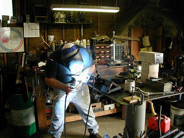
The shop was in full gear now. My friend Ron Polle was making some table keys for the boring machine in the vertical mill. These are to be used to mount a hold-down fixture to the machine table. (more on that soon) In the second photo I am drilling some holes in some parts for the hold-down fixture...


The first photo here shows tacking the hold-down fixture items in place while everything is mounted to the machine table. Not a good practice to do, welding on the machine, but I was just tacking things together. In the next photo I am over on the welding table, finishing up the welding on the fixture...

In these next (2) photos you can see how the hold-down fixture is mounted to the machine table and then mounted to the cylinder to keep it stable during boring. This should really help keep the setup rigid. The chains look like they might do the job, but the last thing you need to happen while boring is to have the cylinder move a little. Also, notice in the second photo that the (2) cast iron parallels are gone and replaced with (2) toolmakers adjusting screws. This helped to aid in aligning the bore up by giving more adjustability to the setup. Now to make the toolholder for actually boring the cylinder...


This photo shows indicating the bore of the cylinder getting the machine spindle on center with it. After this is completed all the table and spindle locks are clamped down. This is quite a tedious process but it needs to be done...

Here is a photo of the toolholder I made for this boring job. It is 3 inches thick and 7 inches in diameter. The carbide cutting tool will be shimed to the center line of the machine spindle and clamped in with 3/8-16 set screws. There is a 1 1/2 inch diameter hole in the center of the toolholder to locate the stabilizer bar and keep the tool vibration down when the machine spindle is in the extended position...

Next I am getting the outboard bearing support on center with the machine spindle by extending the machine spindle and indicating the O.D. of a small shaft in the bearing block. The stabilizing bar will always be engaged in the bearing block and it is very important that it is lined up on center with the machine spindle...

This is a photo of the toolholder, stabilizing bar, and cutter all assembled and almost ready for action. I need to shim the cutter into position and lock it down. Then we can start making some chips...

Page 1, Page 2, Page 3, Page 4, Page 5, Page 6, Page 7, Page 8, Index
for more of the 20 HP Abel Acme Restoration project.
 |
Antique Gas Engine WebSite |
|
 Website designed and maintained by , Pavilion, NY.
Lunarpages Affiliate Program

Registered User #157284
Sun, Sparc, Ultra60 running Aurora 1.0 (RedHat Linux 7.3)
in mind, and are meant entirely for fun. No copyright infringements (if any) are done intentionally.