of the
25 HP Swan Restoration
Continued...
See
Page 1, Page 2, Page 3, Page 4, Page 5, Page 6, Page 7, Page 8, Page 9, Page 10,
for more of the 25 HP Swan Restoration project.


Well in these next 3 photos you can see the Swan is going back together after a lot of the parts being painted. It doesn't seem like much progress is being made but painting is pretty time consuming. Next I will put the head on, and the 6 long tie rods, and then can finish the painting on the main parts of the engine....


In the first photo here you can see the head gasket ready to be coated with "Indian Head" gasket sealer, and for the head and cover plate to be slid on. The next 3 photos are of the head and cover plate all in place and tightened up...


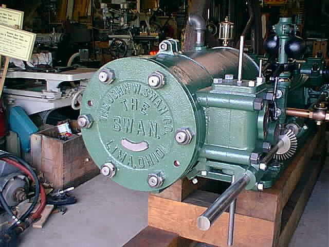
Here are 3 more photos showing the head and cover plate all green now. The engine is taking on a different look being all one color, Green. I have a good 2 coats of paint on the head and cover plate and will put 2 more on it...


The Swan now gets a gas valve and some 1" brass pipe...

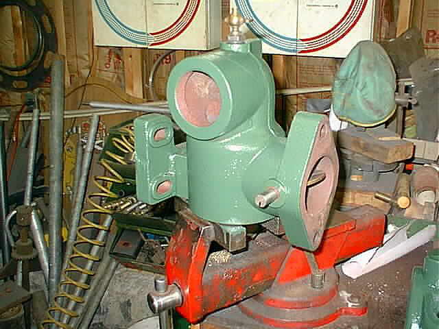
In the first photo here I have put the intake cam on the side shaft and have the rocker arm that will work the intake valve in position. What I am doing here is before I fix the rocker arms up I want to make sure everything will work properly together. In the following 2 photos you can see the long horizontal rocker arm that will work the exhaust valve. Everything looks good, so now to get busy...


I have finally started working on the exhaust valve chest. You can see there is a lot of work to be done on it. In the first photo you can see (4) broken off studs that need to be removed and in the second photo you can see where I cut the old valve off with a hacksaw getting ready to heat the housing and press the exhaust valve out...


After a few minutes of work the exhaust valve is out. As you can see things are rusted pretty bad. I will make a new exhaust valve and recut the seat and things will be just like new...

Now for some more clean up. In these 2 photos I am sure you can see what is taking place. Thats right, more sand blasting. Its a dirty job but the parts look like a million dollars when they are all done...


To get those broken off studs out of the exhaust housing I drilled a 3/8 diameter hole in the center of the stud and then burned the rest of the stud out with the tourch. These are blind holes so you want to be very careful when cutting them out. The tourch will burn the steel stud out and not even hurt the threads in the cast exhaust housing. Next I just ran a 5/8-11 bottoming tap in the (4) holes to clean the threads up and they look just like new...

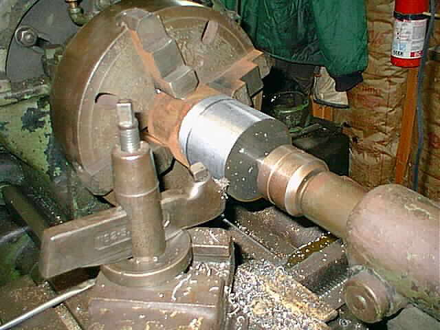
In these 2 photos I started turning the main hub for the exhaust cam. I'm turning it out of a piece of old crank shaft that came off of my 15 HP Reid. If you have ever seen the length of crank shaft on the pulley side of a Reid you know why I cut it down...

After finishing the hub on the lathe I then welded a piece of 3/4 flat stock to the hub, to form the cam lobe. After I get the rocker arms and valves done I am sure I will have to adjust the lobe profile...

Next I drilled and tapped the hub for a set screw...

Here in this photo you can see the new exhaust cam on the side shaft...

Using the heat wrench and good ole elbow grease I started to disassemble the rocker arms. I had to remove the valve adjusting screws and rollers. This wasn't too bad of a job. Now to clean them up for priming. Shown here is the exhaust valve rocker arm...

In the following 3 photos the rocker arms are all cleaned up and get thier first coat of primer. The first photo is of the exhaust rocker arm, the second photo is of the intake rocker arm, and the last photo is of the rocker arm pivot block...


These 2 photos show the rocker arms in place all primed and a new pivot pin installed. The rollers that follow the cams and mount on the rocker arms need to be made next...


In these next 2 photos I am making the roller for the intake cam. The roller is mounted on a mandrel in the lathe and I am putting a 10 deg. taper on the roller face. This will match up with the 10 deg. taper on the intake cam lobe. I believe this taper allows you to control the stroke of the intake valve by where you position the roller and cam. The high side of the taper will give you the max stroke and the low side of the taper will give you the minimum stroke. Hope I am explaining this so you can understand it...


Here I started making the pin the cam roller will rotate on. I need to cut a 5/8-11 thread on the small end and the pin will be complete...

In these 2 photos I have completed making the pin and roller for the exhaust rocker arm. I made the roller out of some stainless steel I had and also notice the oil hole in the middle of the roller. The roller will run in a small bath (sump) of oil, as the rocker arm in that area is all enclosed under the roller...


Next the exhaust rocker arm, intake rocker arm, and the rocker arm mount all get thier first coat of paint...


The rocker arms are all painted and installed on the engine now. Boy are we getting close to firing her up now. I have a bungee cord holding the exhaust valve rocker arm level so it doesn't scratch the new paint. Now to complete the exhaust valve chest...


This is a photo of the intake valve spring and the adjusting bushing and nut completed. Both brass parts are threaded so they can be locked in place. They are the 2 parts on top of the spring in this photo. They look like one piece in the photo but they are actually two...

Here in these 2 photos you can see the intake valve stem, spring, spacers, the adjusting nut, and jam nut in place. They are now all ready for action...


This is a photo of the completed hot tube and chimney. There was not one existing on the engine when I purchased it so I made this one from scratch. I also have a 6" stainless steel hot tube screwed into the top of intake valve chest but you really can't see it in this photo. It is inside the chimney...

Well the Swan finally gets pulled outside. I need to spend a lot of time wire brushing and sanding on the flywheels, so it was time to move the Swan out of the shop. It really was something to see how she sparkled out in the sun light...


Here in this photo my oldest son Joseph took a little time out from working on his 1972 Nova to help Dad do some wire brushing. This wire brushing thing gets old in a hurry. It took a good 2 solid afternoons to get them all cleaned up and ready for primer...

Now the primer gets applied. Also my youngest son Christopher is now helping with this task...


The first photo was taken after one coat of primer was applied. The next 2 photos were taken after 2 more coats of primer where applied and now I am going to start wet sanding the flywheels...


The flywheels get some green paint. In the following 4 photos you can see my son and I have put the first coat of green paint on the flywheels. This is really changing the way the engine looks. Where you can still see primer on the rims of the flywheels, this will be painted black...


See
Page 1, Page 2, Page 3, Page 4, Page 5, Page 6, Page 7, Page 8, Page 9, Page 10,
for more of the 25 HP Swan Restoration project.
 |
Antique Gas Engine WebSite |
|
 Website designed and maintained by , Pavilion, NY.
Lunarpages Affiliate Program

Registered User #157284
Sun, Sparc, Ultra60 running Aurora 1.0 (RedHat Linux 7.3)
in mind, and are meant entirely for fun. No copyright infringements (if any) are done intentionally.