of the
25 HP Swan Restoration
Continued...
See
Page 1, Page 2, Page 3, Page 4, Page 5, Page 6, Page 7, Page 8, Page 9, Page 10,
for more of the 25 HP Swan Restoration project.

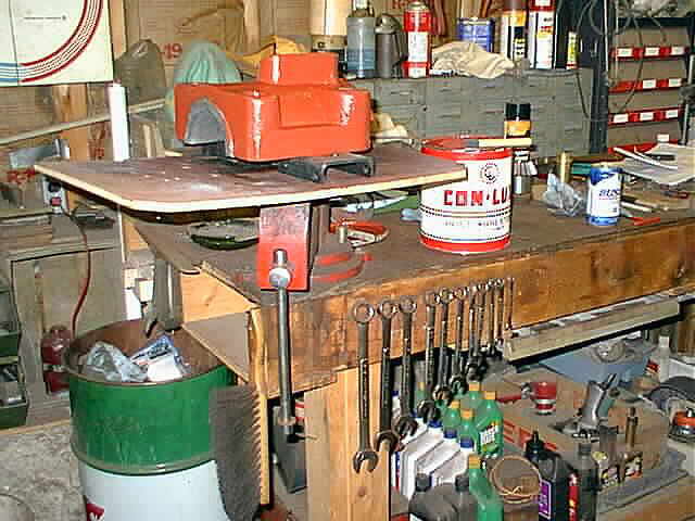
The pull bars for the skid are now all completed and just waiting for the paint to dry. Also in the third photo the flat plates are completed too...


Here the tops of the cross head slide get a coat of primer to keep them from rusting. Cast iron after sand blasting seems to start instantly rusting...

In these 2 photos I now have the studs in for mounting the cross head slide tops ...


With the paint all dry on the pull bars I mounted them on the skid. The following 4 photos show the pull bars mounted on the skid front and rear...


This is the flat valve that will shut the gas off when the engine is not on the intake cycle. In this photo I am getting ready to weld it to the stem...

These are a couple of photos of turning the valve in the lathe. I had to take light cuts to turn the OD because the material in only .060 thick. The last photo here shows the lathe work all completed...


The next step was to rivit a piece of rubber to the valve. In these 2 photos you can see the brass rivits holding the rubber to the valve. The original valve had rubber rivited to the valve and I think they used rivits in stead of screws because if a screw came loose it could get sucked right into the combustion chamber...


Well I needed to take some measurements from the crank shaft to the cross head so I put the crank shaft and flywheels back on the engine base. These 4 photos just show the crank shaft and flywheels going back on...


Here the cross head gets its first couple of coats of primer. The cross head will eventually be painted black. It is hard to see in the photo but I have some areas taped off where I don't want primer to get..

In these 3 photos you can see the cross head all painted. The last 2 photos here show the cross head mounted on the engine. I get pretty excited seeing things go together and now with paint and some color starting to show on the engine, it brings even more excitement...


Well the bearing caps finally made it to getting sand blasted. I cleaned them up real good and applied some good healthly coats of primer. In the last photo the bearing caps are on the engine. I need to figure out what color I am going to paint the swan!...


This is the connecting rod that goes from the cross head to the crank shaft all sand blasted and primed...

Here are the strap, wedge, and brasses for the cross head side of the connecting rod. They are all cleaned up and ready for installation...

In these next 2 photos you can see how I have the engine jacked up so I can winch the skid under the base. This was a little tricky but I took my time and tried to make a stable set up for getting the skid under the engine...


There was a small crack in the flange on the base so I veed it out good and nickel welded the crack. Then I put some filler on the weld to clean its appearance up...

One thing I did before lowering the engine base on the skid was to put a layer of plastic down so I wouldn't get any primer or paint on the skid...

In these 2 photos you can see the bearings and connecting rod assembled into the engine. I need to make bearings and a strap clamp for the rear connecting rod so assembling this allowed me to take some measurements...


This is the start of the bearing strap. In this photo I am just squaring up the material and am going to cut a 45 deg. angle on the side for welding. The strap will be made out of 3 pieces...

The following 3 photos are different views of the engine on the skid. The mounting hardware is all in place and the engine is starting to look huge...


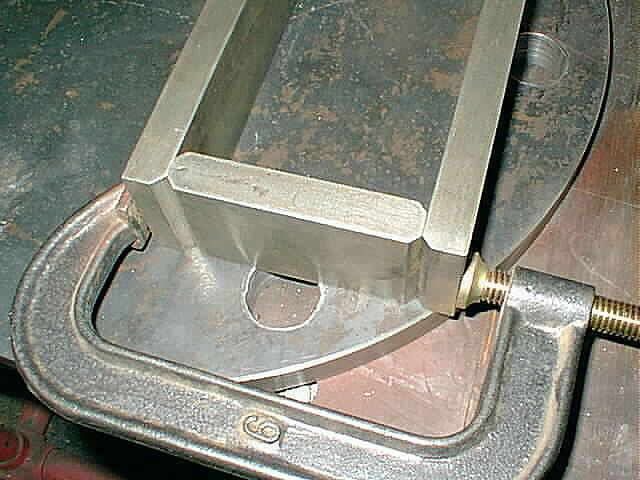
Here in these 2 photos you can see the 3 pieces that will make up the bearing strap for the rear of the connecting rod (crank shaft side). I machined 45 deg. angles where I need to weld it and have it all clamped up and ready for welding...

For holding the cylinder sleeve in place I made (2) 1/2 - 13 T-Bolts. They will hold the sleeve in place while the water jacket, valve chest, and head get assembled. When the assembly is completed I will remove the T-Bolts and fish them out from between the water jacket and the sleeve. This will have to be done before the top 2 tie rods are put in. The T-Bolts are currently in the same holes that the tie rods need to go into...


Using an engine lift I hoisted the water jacket up into position over the cylinder sleeve for assembly. I picked up the water jacket by putting a clevis in the cooling water outlet hole because it is located in the center of the jacket. After getting the water jacket almost into position I changed over to a nylon strap around the outside. This allowed me to skoot the water jacket towards the engine base into its final location ...


In this photo the water jacket installation is complete. There are (2) bolts, one on either side, that hold it in place till the (6) tie rods are installed with the valve chest and head to sandwich everything together...

Here I stuck the side shaft on the engine to check the drive gear location. Once the valve chest gets mounted I can pour the babbitt for the side shaft. There is a third mount on the valve chest for the side shaft that needs to be installed before the babbitt can be poured...

These are 2 photos of the welded up bearing strap. A friend of mine Dave Johnson of Corfu, New York who owns a machine shop welded the strap for me. The material for the strap is 3/4" thick and my Miller 185 mig welder might not have had the power to penitrate and get a good strong weld. I didn't want to take chances on this part with its function...


I wasn't happy with the surfaces of the connecting rod where the bearing strap will fit over so I set it up in the shaper and took a couple of skim passes. Believe it or not these 2 surfaces on the connecting rod weren't even parallel. Now they are...

Here the head cover plate is all sand blasted and cleaned up. In the second photo you can see a nice coat of primer on the plate...


See
Page 1, Page 2, Page 3, Page 4, Page 5, Page 6, Page 7, Page 8, Page 9, Page 10,
for more of the 25 HP Swan Restoration project.
 |
Antique Gas Engine WebSite |
|
 Website designed and maintained by , Pavilion, NY.
Lunarpages Affiliate Program

Registered User #157284
Sun, Sparc, Ultra60 running Aurora 1.0 (RedHat Linux 7.3)
in mind, and are meant entirely for fun. No copyright infringements (if any) are done intentionally.