Page #2
of the

This engine is a 4 cycle cross head
designed engine with an 11" Bore & 18" Stroke.
There is one huge 5 1/2'
diameter flywheel. The engine was the fore runner
to both the Buffalo and Titusville Olins.
Page 1, Page 2, Page 3, Page 4, Page 5, Page 6, Page 7, Page 8, Index
for more of the 20 HP Abel Acme Restoration project.
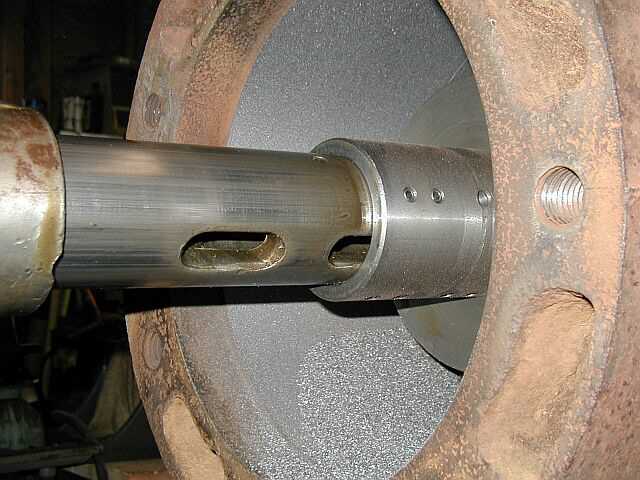
Well we actually started boring the cylinder. These (2) photos are of the first few passes through the bore, only hitting the high spots. If you look close in the first photo you can see the toolholder about half way through the cylinder bore. I am running at 20 rpms with a .014 feed rate. In the second photo you can see the back side of the toolholder as it travels through the cylinder bore...


Here in these next two photos you can see the early stages of starting to bore the cylinder. In the first photo, this is the best part of the cylinder, which has never seen any piston travel. You can see a nice even cut. In the second photo you can see the pitting in the cylinder...


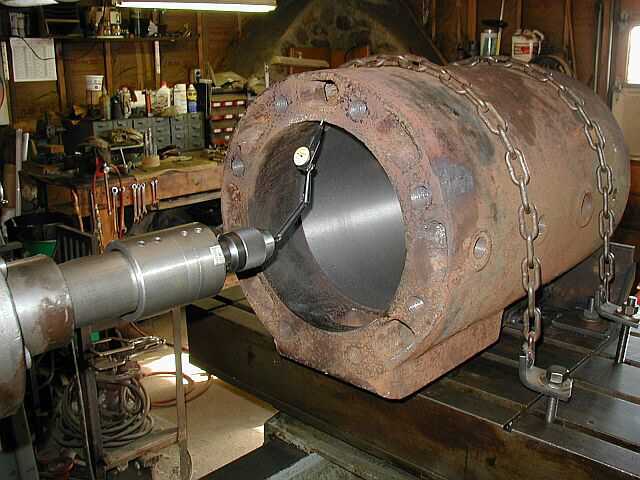
This photo, although you can't tell, is of taking a rough pass through the cylinder bore. It shows the entire set-up and the Lucas boring mill in action...

I took these two photos from the outboard bearing side of the cylinder, which is the head end. You can still see some pitting. I am still running at 20 rpms with a .014 feed rate and have made about 7 passes now...


This is the second to last pass through the cylinder still running at 20 rpms with a .014 feed rate but notice that all the pitting is gone...
Here it is! The boring is completed! Now to hone the bore and do some more measuring to see what the piston has to be metal sprayed and turned to. Before I take the cylinder off the machine, I am going to face each end where the cylinder mounts to the engine base and where the head mounts. The first two photos are of the completed bore with the toolholder and stabilizing bar still in place. Then in the last two photos I removed the toolholder, stabilizing bar, and bearing support to get a better look at the bore. In the last photo, the hash marks are how many passes I made through the cylinder. The last (finish) pass was done at 20 rpms with a .004 feed rate which took 1 hour and 10 minutes to complete. I am very happy with how the cylinder bore came out and didn't run into any vibration problems which I was worried about...


Well it was time to measure the cylinder and see where it wound up. In the first photo my friend Ron Polle measured the bore and after comparing it to the original numbers we removed .086 of material. I also ran an indicator down the bore again in all four quadrants to see if there was any taper in the bore. You can see this in the second photo. There was about .0025 taper from one end to the other. I didn't think that was to bad...


The next step was to mill the surface the cylinder mounts to the bed plate on. This was in rough shape with quite a bit of pitting. By milling this surface will also ensure that it is perpendicular to the new bore. In the first photo Ron is milling a drive disk for the toolholder we made. The second photo shows the toolholder we made and also the cutter. The third photo shows everything all assembled...


These (2) photos show the tool all mounted in the machine spindle and ready for action. Who owns that ugly mug in the first photo? Now to make some cast iron chips...


This photo shows the cylinder mounting surface all machined up nice and flat and perpendicular to the new bore. What a big difference this all makes. Next I am going to spin the cylinder around and machine the surface the head mounts onto...

Boring & Facing Video clip
Here are a couple of MPG videos of Boring and Facing the Abel Acme Cylinder. They are only around 200K in size and should load real quick. Click the link below for the video you want to see. Right click on the link to save the video to your hard drive...Boring | Facing
Well its time to spin the cylinder around and machine the head end. In the first photo here you can see the cylinder rotated 180 deg. and being indicated to square up the original mounting face. In the second photo you can see the cylinder resting on a parallel where the valve chest mounts and then my adjustable cradle on the other end. Also I stabilized the cylinder by mounting the hold-down fixture to it...
In these (2) photos you can see the head mounting face all machined. I took a total of 3 passes and removed about .043 to get almost all the pitting removed. The next step will be to stand the cylinder on end and machine the valve chest mounting surface...


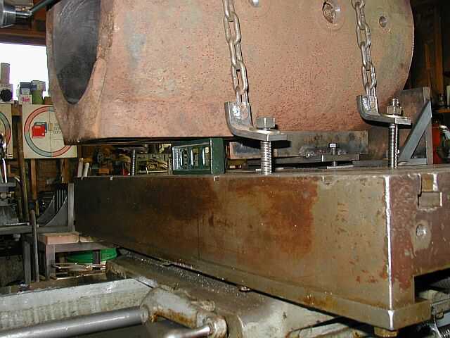
The first (2) photos here show the cylinder rotated and standing up on the head mounting surface. Note that the cylinder is sitting on (3) points (parallels). For clamping the cylinder to the table I used "T" nuts and threaded rod with a plate on top to lock everything down. Before tightening the clamps down, I indicated the valve chest mounting surface to square things up...


After all the setup was completed I was ready to make some chips. The first photo was taken after the first pass was finished. I removed .012 the first pass and you can see in the photo that a lot of the pitting was still very visable. The last (2) photos are after I took the second pass of .015 for a total removal of .027. The pitting is almost 100% gone after the (2) passes. Next I am going to drill the (6) valve chest mounting holes and repair the threads while the cylinder is all setup on the horizontal boring mill...


Page 1, Page 2, Page 3, Page 4, Page 5, Page 6, Page 7, Page 8, Index
for more of the 20 HP Abel Acme Restoration project.
 |
Antique Gas Engine WebSite |
|
 Website designed and maintained by , Pavilion, NY.
Lunarpages Affiliate Program

Registered User #157284
Sun, Sparc, Ultra60 running Aurora 1.0 (RedHat Linux 7.3)
in mind, and are meant entirely for fun. No copyright infringements (if any) are done intentionally.